Home

Lucios fă un experiment Portret lr filter bode plot Cumpără Învăţare magazin

RC-RL Filters
RC-RL Filters

Fil:Butterworth filter bode plot.png – Wikipedia

Passive High Pass Filter - Passive RC Filter Tutorial

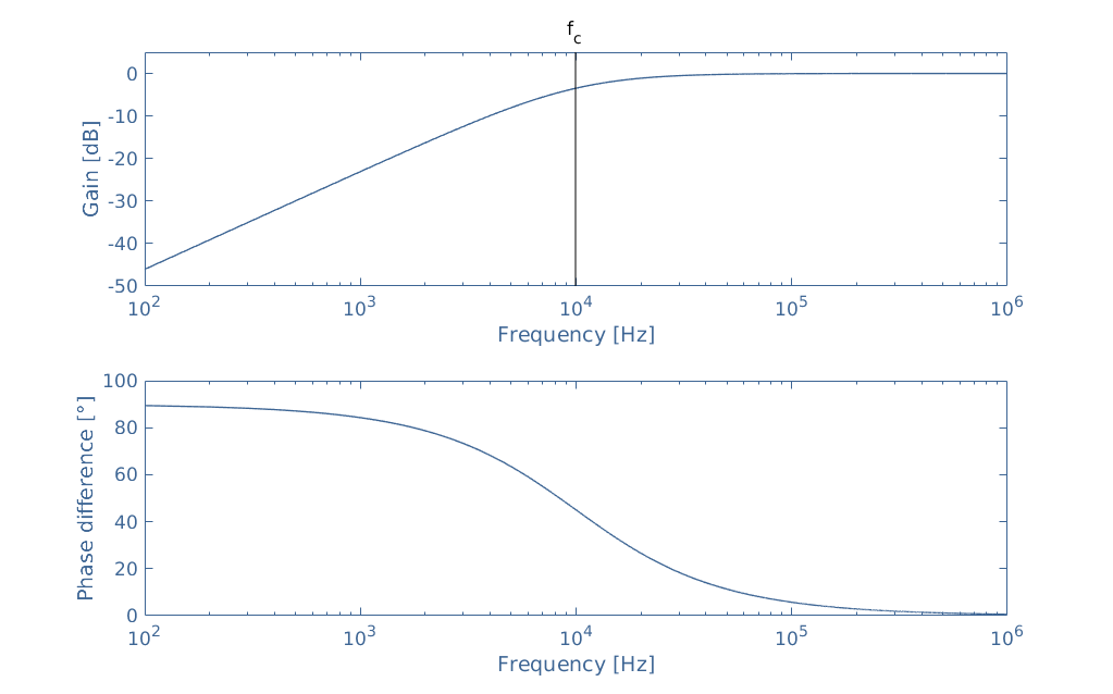
Bode plot for first order high pass (RL) - reality vs theory

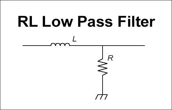
RL Low Pass Filter Calculator

Energies | Free Full-Text | Experimental Investigation of the Frequency  Response of an LC-Filter and Power Transformer for Grid Connection
Energies | Free Full-Text | Experimental Investigation of the Frequency Response of an LC-Filter and Power Transformer for Grid Connection

Filters - Low Pass and High Pass | CE Distribution

Passive Low Pass Filter - Passive RC Filter Tutorial

Bode Diagrams - Electronics-Lab.com

Bandpass Filter Bode Plot and Analysis

circuit analysis - LC low pass filter: intuitive understanding - Electrical  Engineering Stack Exchange
circuit analysis - LC low pass filter: intuitive understanding - Electrical Engineering Stack Exchange

BODE PLOTS FIRST <wm Fll.,TERS (RC or I.R) 20 -40

Bode diagram of the low-pass filter at the inverter output. The diagram...  | Download Scientific Diagram
Bode diagram of the low-pass filter at the inverter output. The diagram... | Download Scientific Diagram

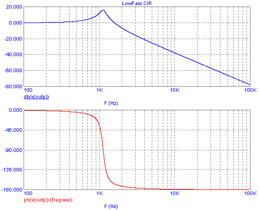
Bode Plots for Second-Order Lowpass Filters with Corner Resonance

Filter Bode-plot at different loads. | Download Scientific Diagram

Bode Plots for Second-Order Butterworth Filters

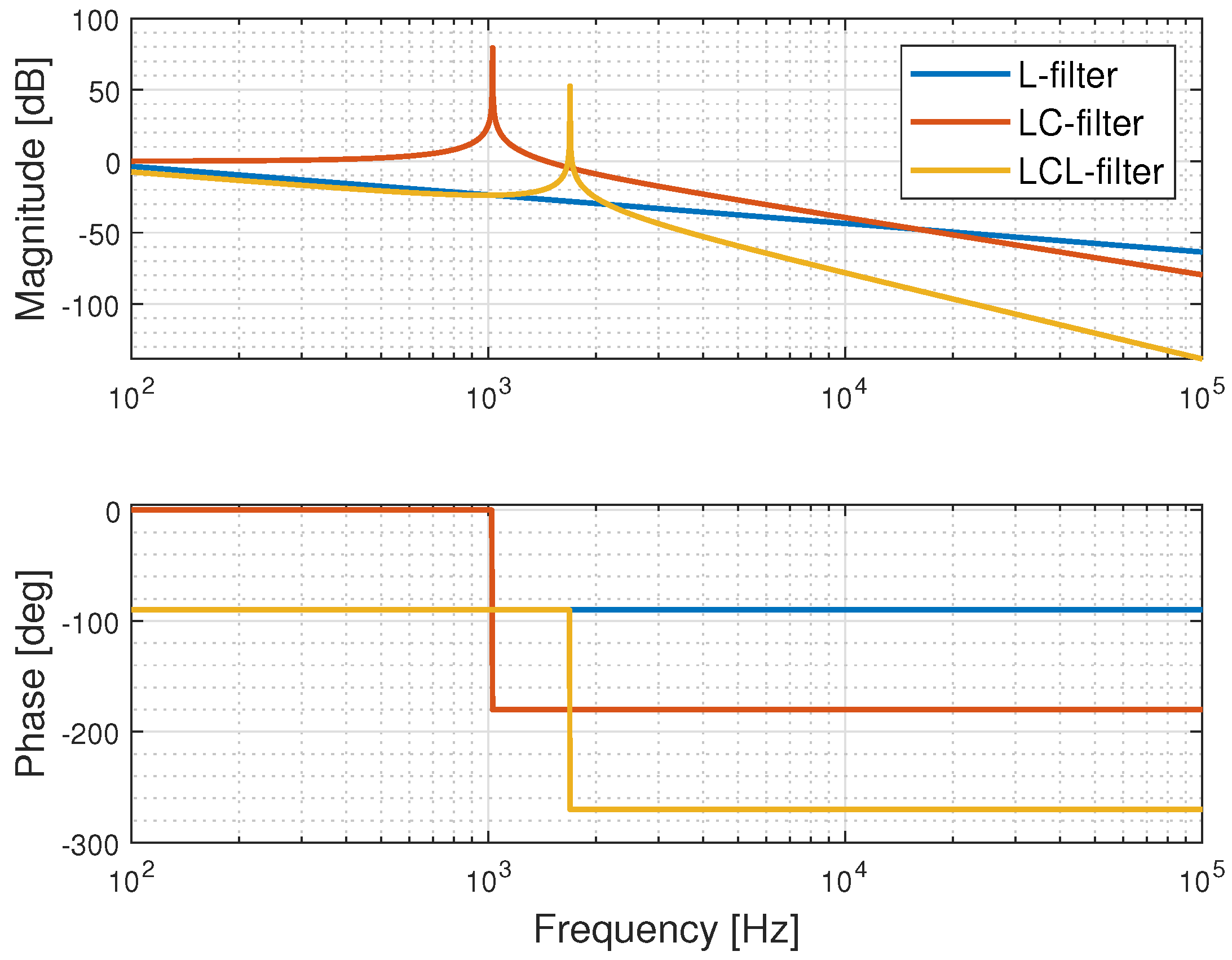
Figure 3 from Design of LCL filters for the back-to-back converter in a  Doubly Fed Induction Generator | Semantic Scholar
Figure 3 from Design of LCL filters for the back-to-back converter in a Doubly Fed Induction Generator | Semantic Scholar

8.6.2. RLC Filter — PySpice @VERSION@ documentation

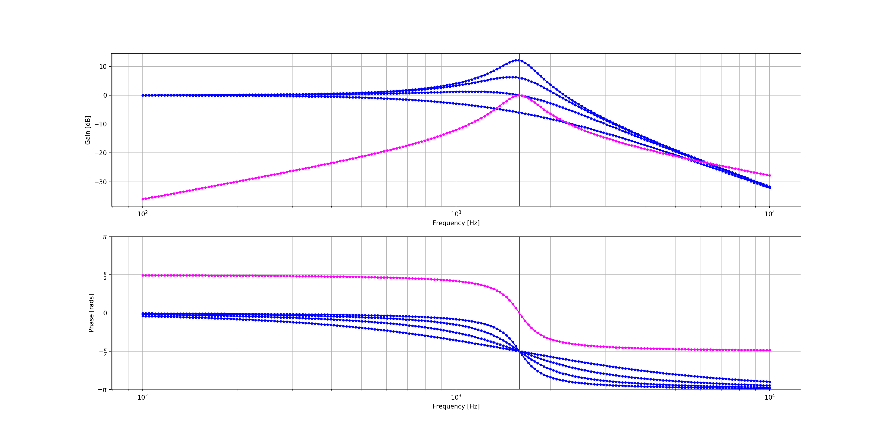
passive networks - RLC Low-Pass Filter with MATLAB - Electrical Engineering  Stack Exchange
passive networks - RLC Low-Pass Filter with MATLAB - Electrical Engineering Stack Exchange

Bandpass Filter Bode Plot and Analysis

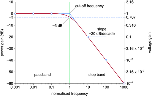
Electronic applications: 2.5 Normalised first-order low-pass filters |  OpenLearn - Open University
Electronic applications: 2.5 Normalised first-order low-pass filters | OpenLearn - Open University

Analyzing the Response of an RLC Circuit - MATLAB & Simulink

Control loops
Control loops

A bode plot shows the frequency response of the LC, which is used in... |  Download Scientific Diagram
A bode plot shows the frequency response of the LC, which is used in... | Download Scientific Diagram

BODE PLOTS FIRST <wm Fll.,TERS (RC or I.R) 20 -40

Bode Diagram of the Second Order IIR Butterworth Band Pass Filter |  Download Scientific Diagram
Bode Diagram of the Second Order IIR Butterworth Band Pass Filter | Download Scientific Diagram